 |
ARTICLES |
|
USB 2.0 Printed Circuit Board Design |
High-speed Chirp
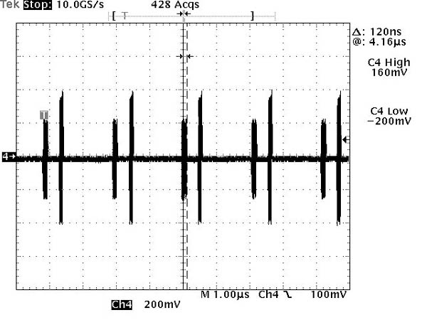
A device and host use a handshake to indicate they are high-speed capable. The high-speed device begins the handshake by signaling a high-speed chirp. If the host controller or hub supports high-speed, it detects the chirp and responds with its portion of the handshake, initiating high-speed communication. Otherwise, it does not detect the chirp, and thus does not respond, and full-speed communication ensues. An example of the high-speed detection handshake sequence is shown in Figure 3.
 |
In compliance testing, the chirp transmitted by the device is measured to verify that it meets the necessary timing, voltage, and high-speed termination requirements to be compatible with other devices.
High-speed Receiver Sensitivity
With the lower signaling levels in high-speed mode, the sensitivity of the receiver is an important characteristic. The receiver must interpret incoming signals as valid only if the voltage levels are above a minimum level and disregard data under that level as noise. Receiver sensitivity is tested after placing the device into another test mode. In this mode, the device responds with a NAK packet to any received IN token. A data generator repeatedly sends IN tokens to the device under test (see Figure 4). The signal level of the IN token is lowered until the device stops responding. The voltage level at which the device stops responding is used to determine if the device's receiver meets the sensitivity requirements.
 |
Copyright(C) 1996-2001 CQ Publishing Co., Ltd.