 |
ARTICLES |
|
PCB Design for New I/O Interface "InfiniBand" |
InfiniBand Layers
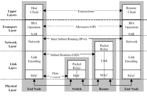
The InfiniBand architecture is divided into multiple layers where each layer operates independently of one another. As shown in Figure , InfiniBand is broken into the following layers: Physical, Link, Network, Transport, and Upper Layers.
 |
Physical Layer
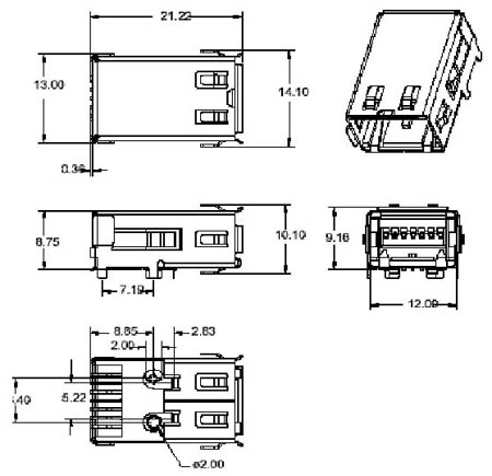
InfiniBand is a comprehensive architecture that defines both electrical and mechanical characteristics for the system. These include cables and receptacles for fiber and copper media; backplane connectors; and hot swap characteristics.
 |
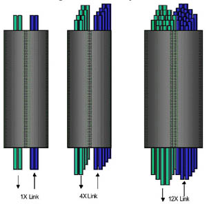
InfiniBand defines three link speeds at the physical layer, 1X, 4X, 12X. Each individual link is a four wire serial differential connection (two wires in each direction) that provide a full duplex connection at 2.5 Gb/s. These links are illustrated in Figure.
 |
The data rates and pin counts for these links are shown in Table.
| InfiniBand Link | Sgnal Count | Signalling Rate | Data Rate | Fully duplexed Data Rate |
|
1X
|
4
|
2.5Gbps
|
2Gbps
|
4Gbps
|
|
4X
|
16
|
10Gbps
|
8Gbps
|
16Gbps
|
|
12X
|
48
|
30Gbps
|
24Gbps
|
48Gbps
|
Note: The bandwidth of an InfiniBand 1X link is 2.5 Gb/s. The actual raw data bandwidth is 2.0 Gb/s (data is 8b/10b encoded). Due to the link being bi-directional, the aggregate bandwidth with respect to a bus is 4 Gb/s. Most products are multi-port designs where the aggregate system I/O bandwidth will be additive.
InfiniBand defines multiple connectors for "out of the box" communications. Both fiber and copper cable connectors are defined as well as a backplane connector for rack-mounted systems.
Link Layer
The link layer (along with the transport layer) is the heart of the InfiniBand Architecture. The link layer encompasses packet layout, point-to-point link operations, and switching within a local subnet.
- Packets
There are two types of packets within the link layer, management and data packets. Management packets are used for link configuration and maintenance. Device information, such as Virtual Lane support is determined with management packets. Data packets carry up to 4k bytes of a transaction payload.
- Switching
Within a subnet, packet forwarding and switching is handled at the link layer. All devices within a subnet have a 16 bit Local ID (LID) assigned by the Subnet Manager. Switches do not need not be cascaded, simply add another switch to expand the fabric.
- QoS
|
QoS is supported by InfiniBand Through Virtual Lanes (VL). These VLs are separate logical communication links which share a single physical link. |
QoS is supported by InfiniBand through Virtual Lanes (VL). These VLs are separate logical communication links which share a single physical link. Each link can support up to 15 standard VLs and one management lane (VL 15). VL15 is the highest priority and VL0 is the lowest. Management packets use VL15 exclusively. Each device must support a minimum of VL0 and VL15 while other VLs are optional.
As a packet traverses the subnet, a Service Level (SL) is defined to ensure its QoS level. Each link along a path can have a different VL, and the SL provides each link a desired priority of communication. Each switch/router has a SL to VL mapping table that is set by the subnet manager to keep the proper priority with the number of VLs supported on each link. Therefore, the IBA can ensure end-to-end QoS through switches, routers and over the long haul.
- Credit Based Flow Control
Flow control is used to manage data flow between two point-to-point links. Flow control is handled on a per VL basis allowing separate virtual fabrics to maintain communication utilizing the same physical media. Each receiving end of a link supplies credits to the sending device on the link to specify the amount of data that can be received without loss of data.
- Data integrity
At the link level there are two CRCs per packet, Variant CRC (VCRC) and Invariant CRC (ICRC) that ensure data integrity. The 16 bit VCRC includes all fields in the packet and is recalculated at each hop. The 32 bit ICRC covers only the fields that do not change from hop to hop. The VCRC provides link level data integrity between two hops and the ICRC provides end-to-end data integrity.
Copyright(C) 1996-2001 CQ Publishing Co., Ltd.